Although there are many variants of the ESP8266 module, I came across ‘Wemos D1 Mini Pro’ a few months back and this is the best module I ever have found. The Major features that led me to say it the best module are:
- Integrated CP2104 USB-TO-UART IC: This makes programming of the module super easy. I have been trying the ESP8266-E01 to program using various USB-To-* modules but had no luck in past 1 year.
- 16M EPROM: The other variant only have 4M memory hence this will allow pushing larger programs. The large memory will also enable you to do Over The Air updates.
- 11 onboard IO: few other variants also have more IO but this is onboard hence you do not need external shield to access IO pins
- Arduino: This module can be programmed using Arduino IDE which is most stable and much easy programming tool I found.
- Dirt cheap: The module is retail at $5.50 + ~$2.0 shipping at AliExpress but if you will buy in bulk from Alibaba then you could get it for <$5 including shipping.
Well, enough bragging let’s start with what we have.
Tools:
- A PC, of course, you need one with USB port and some processing. If you have one you still are using, that will work.
- Arduino IDE (https://www.arduino.cc/en/Main/Software), this is an open source software and is available for Windows, Mac, and Linux. There is a web editor also available but I am not sure how to integrate new boards in it so will not cover that.
- A Micro USB data cable, Required to power the ESP board and upload programs.
- Other Tool: A soldering iron, Jumper wires and may be Multimeter.
Prepare the development environment.
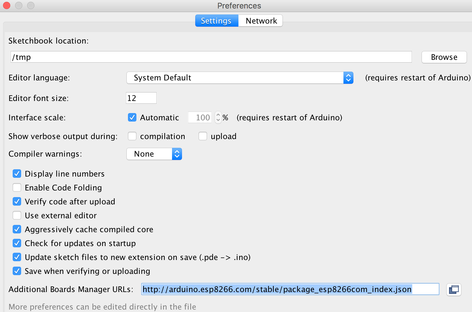
- Open Arduino, Go to Preferences and add URL. http://arduino.esp8266.com/stable/package_esp8266com_index.json
- Now Go to Tools > Board * > Board Manager and type ESP in the filter box.
- Select esp8266 by esp8266 community and click install (Mine is already installed and hence you do not see install button enabled)

- Now should be able to see the esp Modules in the Tools > Board Sub Menu.

- Select Wemos D1 R2 & Mini Module.
- Connect Wemos to USB
- Select the port in Tools > Port
Wemos D1 mini (4M) uses CH340G while D1 Mini Pro (16M) uses CP2104 chip to connect and program your ESP using USB. You may need to visit https://www.wemos.cc/tutorial/get-started-arduino.html to get and install drivers related to your chip and host OS.
Windows:
Windows 10 should install the appropriate drivers as soon as you connect the Wemos module, if not you may need to download and install drivers from the link mentioned above.
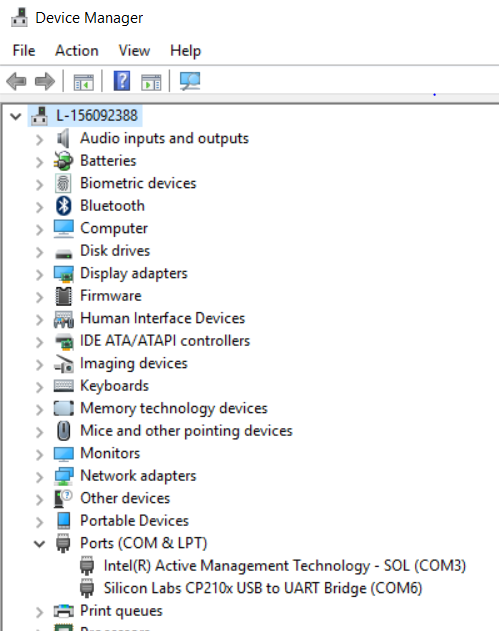
Once drivers are installed, open Control Panel > Device Manager and find USB to UART under ‘Ports (COM & LPT)’ jot down the Port number shown as COMx (eg COM6).
Open Arduino IDE and select the jotted port from Tools > Ports list.
Mac:
Install Mac drivers corresponding to you chip from the link mentioned above.
Connect the Module through USB.
Open Arduino IDE and under Tools > Port the serial port should appear as *USBtoUART. Select the port.

(The Unix-based OS will have steps similar to Mac OS, but as I do not have any active Linux machine, I could not steps and screenshots)
After all these done, you are good to go with programming your ESP module.
Test your ESP module and upload your first Program.
In this step, we are going to take blink sample and upload to ESP to test if the module is any good and will also see in brief the structure of the program.
- Open Arduino IDE (I believe you already have it open)
- Open Blink program from File > Examples > 01.Basics > Blink
- Upload the program to ESP module using the button
in the Toolbar.
- You would see the progress in the Output Window (the black are at the bottom of the IDE) Verify that the image is successfully uploaded.
- Once uploaded the board should auto restart and your program should start executing. Check then led on the board continuously turns on / off with a delay of a second.
Code:
A quick explanation of the Arduino program.
The Arduino program constitutes of 2 basic functions/Methods/Procedures (whatever you want to call it):
void setup(): This is the procedure gets executed once only in the runtime of the program and that too when the board is powered or the reset button (the small push button on the side of USB connector) is pressed. You should be writing your program initialization code in this section.
void loop(): This procedure will be called repeatedly after completion of the previous cycle (By this I mean that the loop is not asynchronous). You would write your core execution logic here.
Inside these procedures, you might be curious what the keyword means.
pinMode(): as I mentioned earlier the board have GPIO pins, the pinMode procedure does set function of the pin. The procedure accepts 2 params pin name and mode. Mode = INPUT will set the pin in read mode (code can read data from the register) for code and the mode = OUTPUT will set the pin in write mode (code can write data to the register). In most of the cases we need to define the pin to a variable but in this sample, the var LED_BUILTIN is predefined by Arduino and refers to default LED on the board (Although this is not a physical pin but refers a register). Hence in the setup() procedure, we are defining the LED pin to initialize that in write mode.
digitalWrite(): This procedure also accepts 2 parameters the pin name and value. The Value can be HIGH or LOW constant when value HIGH is passed that will enable voltage >3 V on that pin causing LED to glow and when LOW is passed it will reduce the voltage < 3V hence cause LED to turn off.
delay(): this procedure holds the execution to specified number of milliseconds. The parameter passed to it is milliseconds value (FYI, 1 second = 1000 milliseconds).
Hurray….
Your ESP Module, Your PC and more importantly You are all Set-Up to develop IOT modules.
PS: Please don't mind me being very detailed, I am writing this keeping my 12 year old in mind.
What's Next: Build your first connected module.
No comments:
Post a Comment